
 The PE Light S
Smart City system
A system for individual requirements
PE-LIGHT-S
Download our Smart-Up-Your-City whitepaper now.
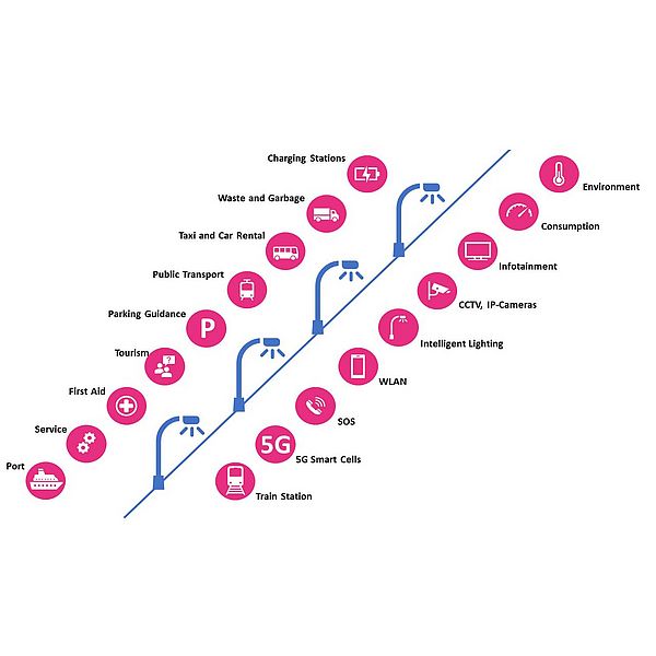
Upgrading light poles and other metal poles to network nodes
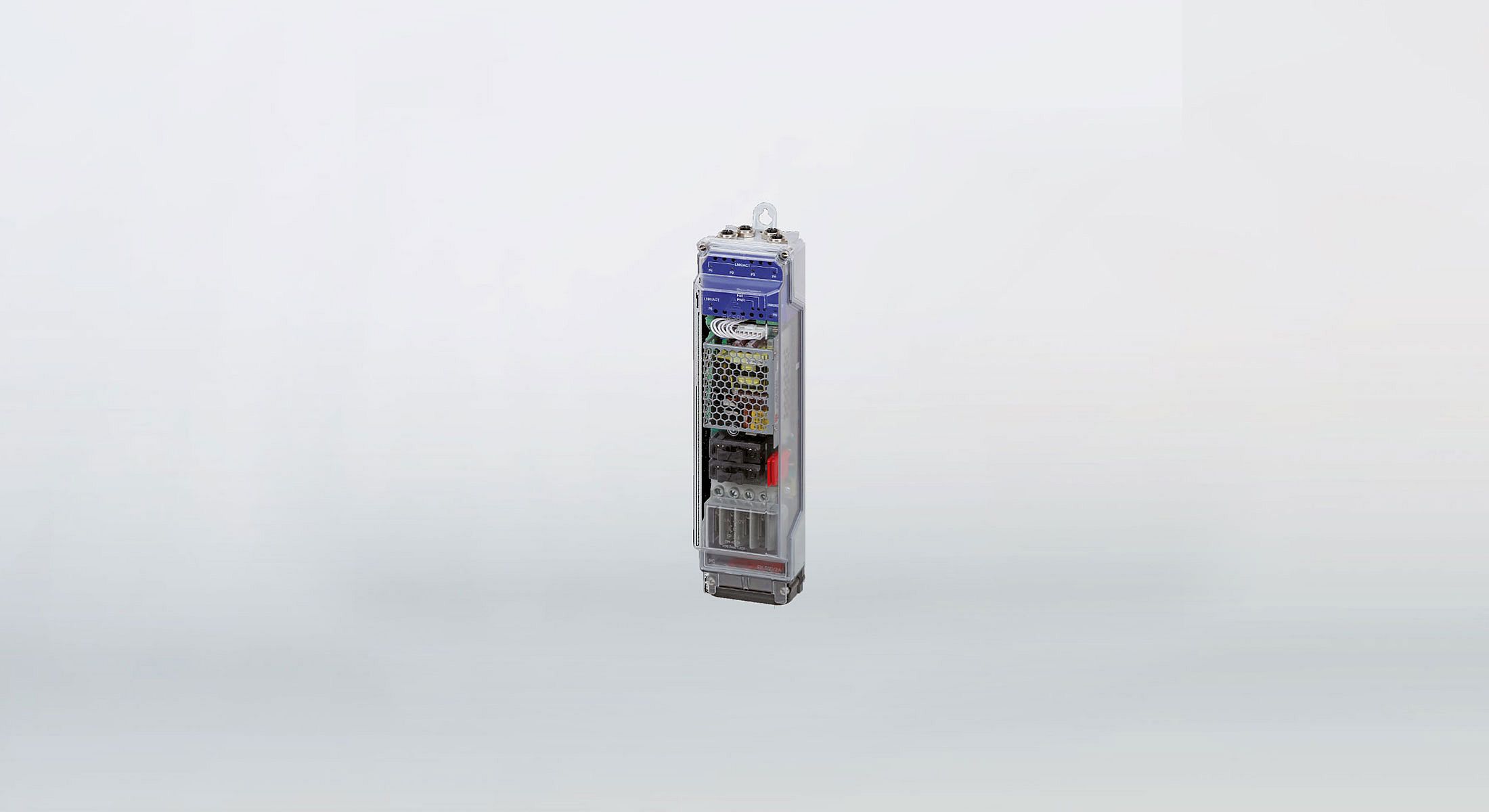
The ultra-compact, modular and multifunctional Smart City System "PE Light S" can be integrated like a classic cable junction box into lighting poles as well as other metal poles - unlike conventional outdoor networking solutions - this makes installation and maintenance very easy. According to "Humble Lamppost" approach, it can be used to connect IP-capable terminals to high-speed networks via fiber optic cables and to supply them via high-power PoE.
The control center of the Smart-City system is a Gigabit Ethernet switch which, like the other system components, is based on proven technology for industrial automation. Thanks to an intuitive user interface, it can be easily configured and monitored without special IT knowledge - both via PC and mobile devices such as smartphones and tablets. Ring redundancy mechanisms and extensive diagnostic options ensure high network availability. Furthermore, tailor-made versions of the Smart City system can be implemented to meet the specific requirements of the customer.
Modular Smart City system
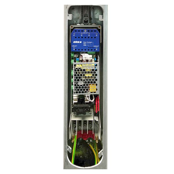
The "PE Light S" consists of a managed Gigabit Ethernet switch, a splice cassette, a power supply unit, fuses and terminals for connecting the supply line. All components are mounted in an ultra-compact IP42 housing (82 mm x 369 mm x 84 mm). This allows the Smart City system to be integrated into metal poles, for example for street lighting or traffic lights, with an internal diameter of at least 100 mm and a door cut-out of 400 mm x 85 mm. Thanks to proven technology for industrial automation, it can also withstand harsh environmental conditions.
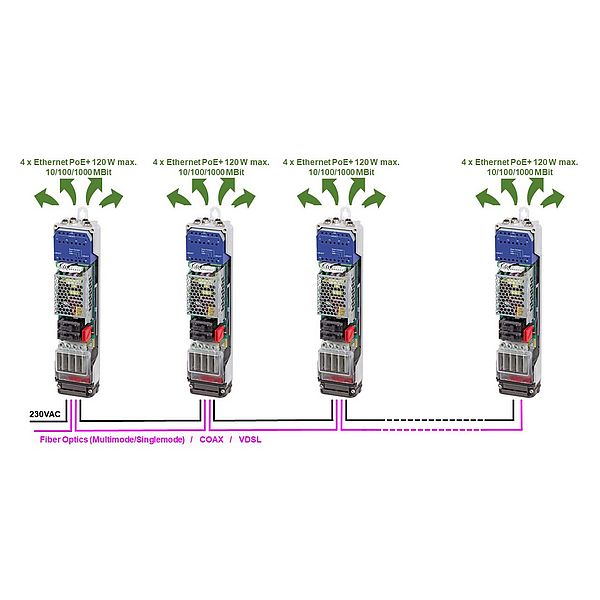
The switch has four electrical ports that support Gigabit Ethernet (10/100/1000 BASE-T) and High-Power PoE (Power over Ethernet according to IEEE 802.3bt with single and dual signature), as well as two optical Gigabit uplinks (1000 BASE-SX/LX) for single or multimode fibers. As a result, up to four IP-capable devices can be connected to a network over distances of up to 10 km and supplied with power at an output power of up to 60 W per port. To forward data and power from one system to another, the terminals for the supply line have an input and an output.
Thanks to its modularity, the Smart-City system also offers an optimal solution for step-by-step broadband expansion. For this purpose, the housing can initially only be equipped with the splice cassette and the terminals. In this way, the fiber optic cables can be safely accommodated in the masts - otherwise the sensitive fiber cores would dangle more or less unprotected inside - and the supply line connected. If the masts shall become network nodes, the switch as well as the power supply unit and fuses can easily be retrofitted.
Easy installation and maintenance
Depending on the network topology, one fiber optic cable (point-to-point and star structure) or two (line and ring structure) are inserted into the housing of the Smart City system and are then spliced in the splice box with the free end of the pigtails supplied, which can be connected to the switch with pre-assembled LC connectors. The switch converts the optical signals into electrical signals and transmits them to the end devices via the RJ45 ports, which have X-coded M12 connections.
Then the supply line of the mast is connected to the Smart City system. From there, two separate lines go up, which have a switched phase for the light and a permanent phase for the terminal devices. If these are PoE-capable, they can be supplied with power via the data cable at the same time, which means that only one power line is required. Finally, the housing is attached to the pole with hooks and its door is locked again.
In case of service, the electronic components of the Smart-City system or parts of the wiring can easily be replaced. Unlike the networking of surveillance cameras, for example, where the connection technology is usually installed in a weatherproof housing attached to the top of the mast, it is not necessary to bring an access platform every time for the installation of pe-light. Furthermore, the Smart City system is completely protected, for example against vandalism.
User-friendly configuration
The switch of the Smart-City system can be accessed via web interface as well as via SNMP (Simple Network Management Protocol) - SNMP is particularly suitable for large networks where it would be too time-consuming to address each switch individually. Since the software supports all browsers and operating systems such as Linux, Windows, Apple or Android, the switch can be managed not only via a PC, but also via smartphone and tablet. To ensure data security, however, access via VPN (Virtual Private Network) and firewall should be used.
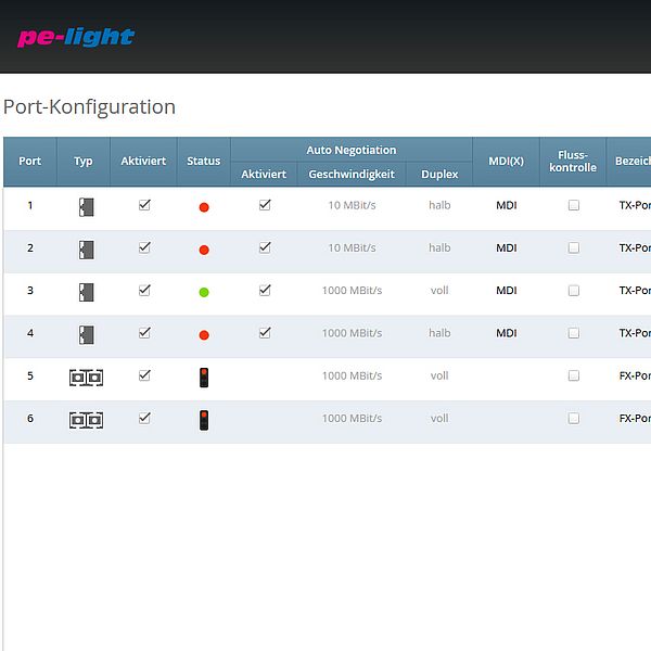
Since the user interface of the switch is similar to operating concepts from the consumer goods sector, it can easily be configured and monitored even without special IT knowledge. Real-time validation checks whether the input of parameters is permitted. Illegal configurations remain grayed out, so they cannot be activated. Changes that have not yet been saved are marked with a blue bar. This makes it easier for the user to maintain an overview, especially in complex menus. In addition, port designations stored in the basic settings are automatically adopted in all menus, making configuration easier and saving time during troubleshooting.
High network availability
The functions of the switch range from Quality of Service (QoS) to reliable ring redundancy mechanisms such as MRP (Media Redundancy Protocol) in accordance with IEC 62439 and - for more complex network topologies - RSTP (Rapid Spanning Tree), as well as extensive diagnostic options that can be adapted exactly to the respective requirements via freely definable escalation levels. They can also be coupled with alarms that are displayed via SNMP, e-mail or relay. In addition, SNMP traps are also possible, with which a previously determined recipient is alerted in case of failure.
Customized versions
Customized versions of the Smart City system are available for special requirements. The customization options range from the design of the housing and its protection class, the number of ports and the type of optical connection technology to industry-specific approvals and the menus of the switch's user interface and its range of functions.
One example is the continuous monitoring of the attenuation of fiber optic lines. If this increases, the data transmission is impaired and eventually fails completely. Reasons can be loose connection elements, dust and dirt, mechanical stress or changes in the network topology. In order to detect this at an early stage, the Smart City system can be equipped with a monitoring function. According to the traffic light principle, the user interface of the switch then displays for each port whether the budget (difference between transmission power and reception sensitivity) of the fiber optic line is in the green, yellow or red range, i.e. whether the defined system reserve is still sufficient.
Smart up
your city.
with eks!


